Design Idea:
Tally information return link over SDI-cables
A professional single SDI (Serial Digital Interface) coaxial cable is usually one way only, transferring digital uncompressed video (and audio) from your video camera to your video switcher.
This idea shows how you can transfer tally information (both preview and program) back to the camera - using the same single SDI-cable. This makes wired or wireless tally systems completely superfluous.
Highlighted features
- Tally information is transmitted to the camera operator(s) via the same SDI cable that transfers camera video (and audio) to the video switcher.
- Both preview and program tally information can be shown.
- No additional active electronics is needed at the camera end.
- Tally information does not interfere with the video/audio stream
- Works with any standard length SDI cables.
- Works with all SDI standards.
- Simpe and cheap to implement.
To start with, here is more detailed information about the SDI-standard:
https://en.wikipedia.org/wiki/Serial_digital_interface
One little known fact is that the SDI interface between the transmitter (camera) and the receiver (video switcher) is usually AC-coupled. There are some exeptions, but they are rare. All tranciever ciruits that are bidirectional are always AC-coupled. This idea doesn't work with DC-connected equipment, but there is noting to worry about if such equipment would be attached to this tally system by accident - they just don't work and nothing is harmed.
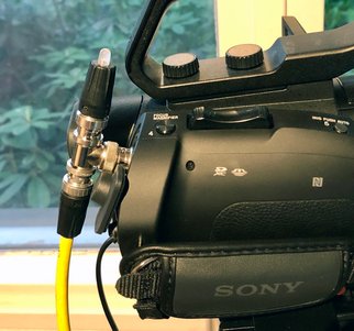
Fig.1 Tally indicator prototype, shown at camera end. It consists of standard parts; one 75-ohm BNC splitter, one bi-color LED, and two passive components inside a 75-ohm BNC-connector. The yellow coax cable goes to the video switcher.
Other Tally solutions
Add-on tally systems and how implement them, can be divided into three problem areas:
- How to pick up the tally information from the video switcher.
- How to transmit the tally information back to the camera.
- How to show or display the tally information to the cameraman, and/or the actors in front of the camera.
Use switchers and cameras from the same vendor (like Blackmagic Design) and the problem is solved, or at least they provide methods or alternatives of how to send tally information to the camera. However, this usually needs additional cabling, or at least multipole cables, of one sort ot the other. And if you are depending on existing hardware, you have to puchase a separate tally system.
This Circuit
This circuit emphasizes on the problems 2 and 3 - how to transmit tally information to the camera, and how to present that information to the cameraman. Problem number 1 is not a part of this design idea (how to pick the tally information from the switcher), even if I have implemented one solution targeting the Black Magic ATEM Television Studio HD switcher in the following article xxxxx.
Detailed Description
It is of utmost importance that the 75-ohm impedance of the coaxial transmission line (as well as the termination resistances) are kept as intact as possible. This is the reason why there are 100uH inductors in series with the DC-signal, both at the tally-driver and the tally receiver. To dampen any resonances and keep the loading consistent, there are mandatory serial resistances (68 ohm) in the lines. They double also as current limiting resistances for the bi-color LED indicator.
Issues
Beware of 75- and 50-ohm BNC-s
Voltage levels, capacitor limitations
Can be induced externally to the sender - or inside the device
Reveiced by a splitter
Can be boosted via optocouplers...

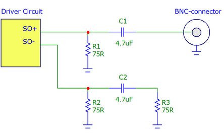
Fig.2 Typical SDI-transmitter schematic. The driver circuit has a differential current driven output that is converted to single ended by shunting the other (unused) ouput in a similar impedance as the cable represents.
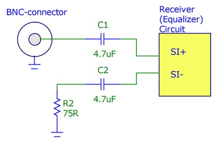
Fig.2 Typical SDI-receiver schematic. The receiver is differential and AC-coupled. The single-sided SDI signal is fed into the receiver using this balancing circuitry. Typically this IC is not only a receiver but an equalizer that boosts the signal high-frequency content, to compensate for the low pass effect caused by long coaxial cables.
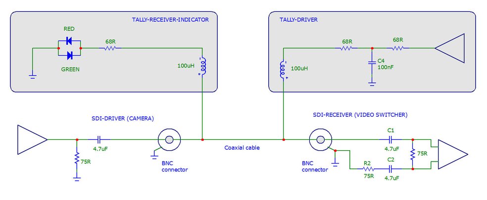
Fig.3 The SDI-tally principle. The SDI-serial video (and embedded audio) is transmitted AC-coupled over a 75-ohm coaxial cable, as shown in the lower part of the picure. Due to the AC-coupling a DC signal can be induced on the cable (acutally in either direction, but here preferably from the switcher towards the camera). If this DC-signal rise and fall times are properly controlled the disturbance of the AC-coupled (video) signal can be kept so low that it does not interfere with the video signal. The add-on tally circuit is shown in the grey boxes.
Addendum
Copyright @ DEXTREL / 2020 / All Rights Reserved