Design Idea:
Isolated High Quality Mains Voltage
Zero Crossing Detector
Highlighted features
- Highly accurate mains zero-crossing detection
- Self-powered, fully isolated low voltage safe output
- Works worldwide at any mains voltage - 100VAC ... 240VAC ±10%
- Low power consumption; worst-case power dissipation < 120mW
- Produces symmetrical pulses around zero crossings
- Output pulse width stays constant, independent of the mains voltage.
- 50Hz mains generates 1ms pulses, 60Hz generates 0.83ms pulses
- Very low parts count, no precision components or tuning required
- All components can be low voltage SMD parts
- Highly stable both with varying temperature and aging
IMPORTANT WARNING
This design contains lethal mains voltage. I cannot be kept responsible for any injuries or deaths caused by not following proper safety precau-tions.
For electrical safety - the layout requires 8mm clearance and 4mm creepage between the isolated and non-isolated sides. If you do not know what that means - then don't attempt to build this design.
Background
Modern electronic equipment is nowadays powered by switchmode power supplies. Due to their high-frequency operation, these PSUs have no means of providing mains frequency (and/or mains phase) information for the low voltage electronics circuitry on the isolated secondary side. Devices such as lighting controllers, thermostats, motor drives, and similar AC-load controlling or monitoring applications, often need mains phase and/or frequency information. Adding an old type iron core mains transformer solely just for this purpose would be both expensive and clumsy. A suitable zero-crossing circuit is often needed. This ZC detector is small, precise, and efficient.
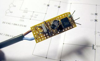
Fig.1 ZCD prototype built using standard through hole components.
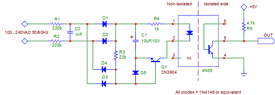
Fig.2 Schematic of the floating, simple but high precision low power symmetric zero-crossing detector circuit.
Other known floating mains ZC-detectors
The Design Idea “Isolated circuit monitors ac-line” published in EDN the 5th of July 2007, is primarily intended for mains line ac-voltage measurement and is not optimal for efficient zero-crossing detection. The Design Idea “Improved optocoupler circuits reduce current draw, resist LED aging”, published 14th of December 2007, also suffers from unnecessary complexity and cannot produce the often required symmetrical zero-crossing pulses for proper thyristor or Triac firing. There is a myriad of other isolated ZCD circuits, but most of them have various shortcomings; either component tolerance sensitivity, sensitive temperature variations, relatively high power dissipation or need high-voltage components, etc.
This Circuit
The circuit presented here produces constant and well-defined zero-crossing pulses, centered symmetrically around the mains zero crossings - using very little power and just a few plain vanilla components. The pulse length is virtually independent of the mains voltage, is stable with temperature, and immune against component and optocoupler tolerances or aging. A perfboard prototype is presented in Fig.1.
Detailed Description
The zero-crossing circuit consists of the voltage to current converting resistors R1-R2, full-wave rectifier diodes D1-D4, a voltage averaging and storing capacitor C1, the optocoupler U1, and the transistor Q1 that functions as a voltage comparator. R3 provides base current for Q1 and doubles as an input voltage divider together with resistors R1-R2. R4 limits and sets the current into the optocoupler LED. D5 provides a proper and well-defined charge current path for C1, also preventing the reverse-biasing of the Q1 b-e junction.
Transistor Q1 stays off during the majority of the mains cycle, during which C1 is charged via R1-R2 and D5. Q1 turns on and feeds current from C1 to the optocoupler via R4, whenever the mains voltage (divided by the ratio (R1+R2)/R3) is one Vbe lower than the voltage across C1. The voltage across C1 will reach in about 200...400ms an equilibrium that defines the final operating point. The voltage across C1 never exceeds 10 volts with the given resistor ratios. The voltage stabilizes at a point when the average current charged from the mains equals the average current consumed by the optocoupler. The typical pulse width is 1ms at 50Hz, and 0.83ms at 60Hz, when using the component values shown. The output pulse width is fairly constant, independent of the designated AC-line voltage (over the whole 100VAC… 240VAC range).
This makes this simple zero-crossing detector quite unique since the mains voltage does not affect the pulse width, nor its symmetry around the zero crossings!
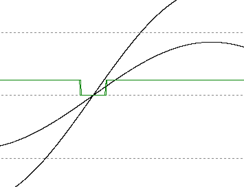
Fig.3 Simulated performance with 115VAC/230VAC input voltages. Note that the output pulse stays symmetrical aound the zero crossing and the pulse width stays virtually the same.
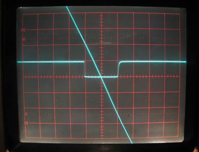
Fig.4 Real world performance. Oscilloscope X-scale is 500us/division, Y-scale is 5V/division for the output, 20V/division for the input (downslope).
The circuit’s total power consumption is small, only 32mW@120VAC, and barely 120mW@240VAC. The majority of this power is dissipated in the input resistors R1-R2. The peak current flowing into the optocoupler LED varies almost linearly with the mains voltage. This does not cause any inaccuracies to the zero-crossing function, as long as the optocoupler output is always allowed to saturate - even at the lowest mains input voltage. This factor determines the minimum allowed value of the pull-up resistor R5. The 4N35 optocoupler has a guaranteed CTR (Current Transfer Ratio) of 100%. If you use another optocoupler, please consider this when calculating the minimum value for R5. You cannot increase the current fed into the optocoupler led by decreasing R4 if you do not at the same time decrease the total resistance of R1 and R2 with the same ratio. The component values given here are optimized for the best signal quality at the lowest possible power dissipation - over the whole international mains AC-voltage range. Do not intend to modify them.
C2 forms together with R1 and R2 a first-order low pass filter to deal with the real world noisy power lines. By decreasing the 1/f frequency of this filter you can filter more serious noise but at the same time, the ZC-pulse will be delayed in relation to the real mains zero crossings. This delay is fixed and can be easily compensated for in the following electronics if any sort of microprocessor is involved.
The voltage rating of C2 can be very low since it sees only the same voltage as C1 plus three diode forwards drops. A 16VDC rating would do (or anything higher).
All components are low-cost and low voltage types (<16V), with the exception that R1 and R2 must each sustain half of the maximum peak mains voltage. Naturally, R2 can be omitted if R1 alone can sustain the maximum peak input voltage. In this case, use a 390kΩ standard 1/4W leaded metal film resistor. Splitting the input resistor into two (halving the voltage - and dissipation handling requirements) makes it possible to use only small SMD-components in the whole circuit.
Fig.3 is a simulated response for two extreme mains voltages (100VAC...240VAC). You can see that the pulse width variation is minuscule, the difference being less than 100us over the whole mains voltage range. The real behavior of the actual circuit is similarly good.
The oscilloscope screenshot (Fig.4) shows the quality and symmetry of the output pulse. The "downhill" trace is the mains voltage at 20V/div vertical scale, zero volts is at the screen centerline. The other trace is the output with a 5V/div scale factor. The timebase is 500µs per division. The output pulse is beautifully symmetric around the mains zero crossings, independently of the mains voltage.
Even large temperature variations have no effect on the zero-crossing pulse, due to the “self-biasing” and digital nature of the circuit. The tolerance of C1's capacitance has no real effect either. If you need a faster startup C1 can be reduced to 2.2uF without problems. The circuit’s resistor ratios set mainly the operation point, and that is the reason is why the output pulse length is almost independent of temperature and mains voltage variations.
Noteworthy observations
- The detector takes a while to start because C1 must initially be charged to its equilibrium voltage. This takes about 200 to 400ms, depending on the mains voltage and the capacitance value. However, after this initial period, the circuit works normally and reacts immediately to missing mains voltage cycles. C1 can be reduced to 2.2uF without any direct effect on the operation.
- This ZC-detector cannot be scaled to be used with AC voltages less than about 80VAC, due to its operating principle. However, it can be used with higher voltages than 240VAC, as long as you scale the input resistors accordingly and make sure that the optocoupler you use fulfills the isolation requirement in your circuit.
- You can use the ZCD with +3.3V logic. Just use it as it is, or optionally replace the pull-up resistor R5 with a 3.3kΩ resistor.
- The output has limited fall time and even slower rise times. Therefore is prudent to use a Schmitt-trigger input to shape the signal, especially if the following circuitry cannot tolerate slow slew rates or jitter (as most of the normal logic gates, especially edge-triggered clock inputs).
- If you only need to comply with ONLY 220/230/240VAC mains, the input resistors can be scaled higher (R1=R2=430kΩ) to reduce the maximum power consumption below 60mW. In this case, the circuit would naturally fail running on 100/115/120VAC mains and lose one of its great benefits (worldwide compatibility).
- All components (with the exception of the two input resistors R1, R2) see only low voltages (<16V). Therefore the diodes, capacitors, and all other components can be low voltage small signal surface mount types.
- To minimize the number of separate SMD components the diode bridge can be constructed using two BAS31 (double) diodes. Likewise, the Q1 and D5 can be combined into one single component - any small signal dual transistor will do where you use the other transistor's CB-junction as a diode to replace D5 (leave the emitter open).
- Make sure to leave enough creepage on the PCB between the mains and output parts. Do NOT use a miniature SMD optocoupler. They cannot provide enough creepage and clearance between the mains voltage carrying part and the isolated output.
- Do not replace the optocoupler with a type with less than 100% CTR (current transfer ratio). This would worsen the efficiency, increase power losses, and require recalculation of the resistor values.
- Detecting highly noisy mains voltage might require that the C2 filter capacitor value is increased (works as a low pass RC-filter together with the input resistors). You can increase this capacitance but please note that the zero-crossing signal will not anymore be symmetric around the real zero-crossing, and also be delayed. This is not a problem if the sole purpose is to detect the mains frequency, and not the exact zero crossing occurrence. However, at a given mains frequency, the phase delay is stable.
- This ZCD circuit can be used for other purposes, for example as an AC-load monitor, see below.
Load Monitoring
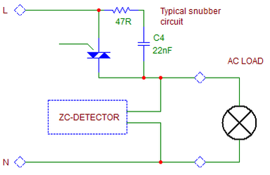
Sometimes you don't need to monitor the mains voltage itself, but rather need to monitor a controlled mains load. Also here the ZCD-circuit comes in handy. An example is shown in Fig 5. Here a Triac controls an incandescent bulb either on or off. With the help of the ZC you can monitor a shorted load, an open load, and/or a missing input voltage, and also check that the Triac is working properly.
When the power to the load is switched off:
There is a small leakage current via the Triac snubber when the Triac is off. This current is effectively shorted by most of the loads, thus the ZCD does not see a big enough voltage to produce any output pulses - if the load is connected. If the load becomes disconnected - or as in this case - the bulb filament has failed - then the snubber leakage current is high enough to produce ZC-pulses even if the Triac is off. This way you can check the condition of the bulb without adding cumbersome current measurement circuits, and get a warning if the load has failed or been disconnected, even BEFORE turning the load on!
When the power to the load is switched on:
During this time the ZCD must produce pulses - if not - then the Triac has failed - or is not triggered properly - or the mains voltage is missing (possibly a blown fuse earlier in the circuit).
By combining this ZCD information with the Triac drive status, you will be able to detect failures when driving a load. Any mission-critical loads (such as alarm lights, traffic lights, motors, etc.) can benefit from this clever and simple load monitoring. Please note that this circuit works best with ON/OFF controlled loads, a phase-angle controlled load would not properly power the ZCD circuit.
Fig.5 Example of load monitoring. The Triac snubber produces enough of current to detect if the load is disconnected. Likewise, the ZC-detector can tell if power is deliveret to a connected load.
Induction-motor rotation monitoring
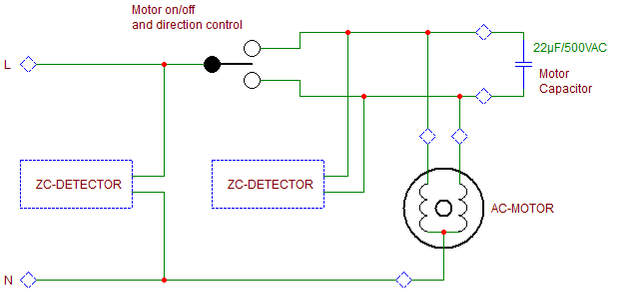
This ZCD circuitry comes in handy also when monitoring the rotation of an AC-motor. Some applications (pumps, fans or various devices requiring a rotational movement) can cause hazards if the motor is not rotating. Instead of attaching some monitoring device to the mechanical axle of the motor, the monitoring can be done directly at the motor driver, as explained below.
The left side ZCD circuit monitors the incoming mains, creating a reference pulse at precise mains zero crossings. The other ZCD circuit is connected across the motor's two windings, producing a pulse at their respective zero crossings. There is a distinct delay between these two ZCD signals that indicate that everything works as assumed. By monitoring the timing relation between these pulses (using a microprocessor or equivalent) you can reliably determine the motor rotation (and even direction of rotation). The difference is precise since the mains frequency is usually very stable. A system can adapt to 50Hz/60Hz mains with clever programming of the microprocessor.
The timing between the pulses from the two ZCD detectors changes from normal if:
- The capacitor has failed (open circuit) - or one or both of the capacitor wires has become loose.
- The capacitor capacitance has changed - or the motor inductance has changed in either winding (partial short circuit).
- Either of the motor windings goes open circuit - or the wire to a winding has become loose.
- The motor is rotating in the wrong direction.
- The motor rotor has stalled (not rotating). The stalled rotor causes a clear phase shift between the two windings (in most AC motors), in relation to the mains phase.
The pulses of the right side ZCD circuit are missing completely if:
- the capacitor has failed (short-circuited).
- the motor common has an open circuit or the wire to the motor has become loose.
- the direction control relay (or Triac) is not closing or the Triac is not firing properly.
- if both motor windings are open-circuited.
This means that ALL possible failure mechanisms are covered with this simple setup. Even the motor controller (ON/OFF and driving direction) is monitored. Note that the circuit works best with hard-driven (ON/OFF) loads, phase angle control might induce very complex waveforms and zero-crossings, making it hard to interpret the ZC signals.
Fig.6 Example of AC-motor monitoring. The left side ZCD circuit is used to measure the mains zero crossings. The right side ZC circuit is connected between the AC motor's windings.
Addendum 1
Some people have had problems understanding the ZCD schematic due to how it is drawn. Fig.2 is drawn correctly but a little awkwardly. My purpose was to cross as few wires as possible. Fig.7 is the mains side of the same circuit, now drawn more traditionally.
Please note that in this schematic the input resistors are not shown (they are still necessary)!
Additionally, the inner workings of the circuit have caused lots of questions. Here are some additional explanations:
Think that the emitter of Q1 is the circuit ground and the mains is a floating input producing alternating sinusoidal current across C2. This current is rectified using diodes D1...D4 (full-wave rectifier). This current charges C1 via D5. During this charging the optocoupler is off - as long as the input current (from the mains) creates a voltage across R3 that higher than the voltage across C1 (plus the diode drop in D5).
Fig.7 Same ZC-circuit but the mains side drawn differently
When the voltage across R3 drops (near the zero crossings) below the voltage across C1 (minus VBE of the Q1 transistor) - then base current starts flowing via R3 into Q1’s base, turning on the optocoupler. Q1 acts thus like a voltage comparator. During the brief periods of the zero crossings current via R3 (because of stored voltage in C1) turns Q1 on. The voltage across C1 finds an equilibrium (works like an integrator) when the power that is drawn during the zero crossings equals the topped power from the mains during the rest of the mains cycle. C1 stores enough energy to be delivered to the optocoupler during the zero crossings. This puts a limit on the C1 capacitance: too low and there is not enough power to feed the optocoupler during the ZC pulse, too high and the ZCD takes too long to settle.
I hope this redrawn schematic and explanation helps to better understand the circuit. Use LTspice or some other simulator to experiment if needed!
Some additional notes:
- Since R1&R2 are connected to the mains - and their other end connects virtually to a very small voltage (about 6...10Volts) you can consider the input resistor(s) as voltage to current converters (U/R = I). Additionally - they limit the input current to a safe maximum. The current fed to the circuitry follows a sinusoidal shape. The "power factor" has no meaning at such small levels but is nice to know that the ZCD does not impose any disturbances or cause any EMC problems.
- R3 forms a voltage divider together with R1&R2 during the time it is disconnected (by the diode D5) from the rest of the circuitry. Additionally, it's actually a pull-up resistor for the transistor’s base (as you can see in the schematic above). It helps to understand the transistor's base circuitry as a current summing junction. Whenever the current flowing from the input resistors is greater than the current (with opposite polarity) flowing via R3 - then the transistor base gets no current. When the situation reverses (closer to zero crossings) the base gets current so that the transistor turns on and current is fed via R4 to the optocoupler from the storage capacitor…
Addendum 2
Here is some of the feedback I have received since publishing this ZCD circuit on my first web page, many many years ago:
DATE: 30.11.2017, FROM: Mike G., SUBJECT: Zero cross circuit
"You Sir, are a genius!"
DATE: 7.11.2017 FROM: Roger, SUBJECT: Love the zero-crosser circuit
"Hi Dextrel, I just wanted to drop you a line to say Thank You" for sharing the zero-crosser circuit. It's a lovely bit of design and beautifully described. Well done, and thank you again."
DATE: 27.10.2017
FROM: Rod E.
SUBJECT: Zero-crossing detector
MESSAGE: "Hi, I wonder if you would allow me to include your ZCD in my existing article about zero crossing detectors (see http://sound.whsites.net/appnotes/an005.htm ). I would not use your original image and would provide full credit to you for the idea. It's an elegant and clever adaption of the basic circuit, and simulations indicate that it will work very well indeed. Cheers, Rod E."
DATE: 14.9.2017
FROM: Samuel B. C.
SUBJECT: DIY Zero-crossing detector
MESSAGE: "Hello, your solution is elegant. May I ask what parameters I have to change to use a 12V AC source?"
DATE: 3.8.2017
FROM: JP M.
SUBJECT: How I got started in electronics
MESSAGE: "I got a similar electric build it set when I was about 8 years old about the year you were born. I got it Christmas Eve and stayed up all night trying to get something, anything, to work. The next day I found out the batteries were dead. I have had a long successful career as an electrical/electronic engineer. Love your zero-crossing circuit! Looking forward to exploring your site".
DATE: 12.11.2016
FROM: Nico de H.
SUBJECT: Thanks for the zero-crossing detector
MESSAGE: "Hi, Just wanted to drop you a line saying thanks for your zero-crossing schematic. I'm going to use it in one of my home automation projects that switches A/C mains using two MOSFETs. Regards, Nico de H."
DATE: 12.11.2016
FROM: Jim B.
SUBJECT: Thanks
MESSAGE: "I want to thank you again, for not only helping me understand your Zero Cross Detector circuit better but also being patient with my learning curve. At the time we communicated, I still did not have sufficient grasp on the concept of reactance, and I was not so clearly able to see 'mini-systems' of components in groups, each doing their thing within your overall circuit. Your ZeroCrossDetection circuit is to me, one of the most eloquently designed, and truly 'engineered' designs I've seen. Pure hardware, robust, and intelligently designed. No more and no less than precisely what is needed to do the job, and do it well. Thank you again-- for your help, and inspiring me as I continue my journey in this field. Warm regards, Jim"
DATE: 22.3.2015
FROM: John
SUBJECT: Zero Crossing Detector
MESSAGE: "Hi, I wanted to congratulate you for designing such an elegant zero-crossing circuit! I don't often envy other people's accomplishments but I certainly wish I had thought of it. Every part counts and, as you point out, the symmetry around the zero is very accurate. Hats off to you! John"
DATE: 24.8.2011
FROM: Manuel
SUBJECT: Zero Crossing Detector
MESSAGE: "Dear, You are brilliant, this circuit is great.. so simple, so robust. so efficient.
I really thank you...... If this world would have more people like you. I would be a greater place to live..... Thanks so much... My Best Regards Manuel E. T.
DATE: 27.12.2010
FROM: Matt G.
SUBJECT: DIY ZERO-CROSSER CIRCUIT
MESSAGE: "Greetings from Columbus, Ohio USA! I can't thank you enough for publishing your brilliant zero-cross detection circuit. In a design I'm currently working on, I needed a way to safely isolate the mains from a microcontroller circuit, but I wanted something more efficient than just putting the optocoupler's LED in series with a resistor. I've looked at a lot of ideas out there, but this one stands far above them all. I just grabbed some perf board and am going to start building the prototype.
I too started into electronics as a child when my father bought my twin brother and me one of those "100-in-1" electronic project boards from Radio Shack. We built all the projects in about a week one summer, then started substituting and experimenting. Then we started bugging dad to take us to the radio supply store, teach us to solder, etc. My profession turned out to be software-related, but I still enjoy digital electronics as a hobby. I especially enjoy microcontroller-based circuits where there are some hardware and software engineering involved.
Thanks again for publishing your solution - I'm looking forward to checking out your other designs and projects!
Cheers,
-Matt
Copyright @ DEXTREL / 2022 / All Rights Reserved

