Design Idea:
Efficient Battery Monitoring Circuit
Highlighted features:
- Ultralow standby current
- Low parts count
- Uses only a single pin at the application CPU
- Battery loading is definable for the measurement
- Adaptable for different operating & battery voltages
Background
In electronic applications where the power is drawn from a battery, it is often necessary to measure the voltage and/or charge level of the battery. This is true for both primary and rechargeable batteries.
To ensure battery longevity it is important that the measurement system does not not consume any power when the batteries are not being measured. Similarly, it is recommended to slightly load the batteries during the measurement to get truthful results. If the application operates directly off the battery voltage then this is a no-brainer and can be achieved with just two resistors. See Fig.1 below.
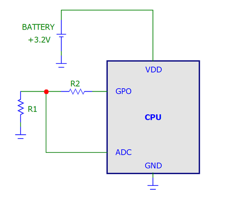
Here you simply pull the general purpose output (GPO) high during the measurement. R1 and R2 scale down the voltage to the internal ADC. Please note that this trick does not work if the ADC inside the CPU is ratiometric and uses the VDD (battery) voltage as the reference. To work this either requires an internal or external fixed reference source. This source produces a reference voltage below the VDD, hence the R1 and R2 resistors are needed to scale down the battery voltage within the input range of the ADC.
The problem gets slightly more complicated if the battery voltage is higher than the processor's VDD. This is common if the battery voltage is regulated down by a switcher or LDO regulator, as in the example below..
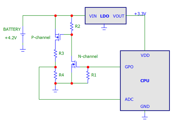
Here R1 ensures that the N-channel MOSFET (and the measurement) stays off when the GPIO pin is in Hi-Z (when the CPU is reset). R1 can be omitted if this is not relevant (the GPIO port always active). R2 ensures that the P-channel MOSFET stays off outside the measurements.
To minimize the loading of the batteries the measurement circuit can be built using high resistance values if kept the circuit all the time. However, this is not without problems due to PCB and I/O-pin leakage currents, susceptibility to interference, and long settling times. Not to mention that in this case the battery voltage measurement is done without loading the battery, which makes it hard to find failing batteries having still acceptable voltage but increased internal resistances.
The measurement circuit can be switched in, it requires one control pin on a processor, controlling a pair of small signal logic level MOSFET-type transistors (one N-channel and one P-channel), as shown in the figure below. The center of the resistor divider is brought to another processor pin where an internal ADC converter converts the measured voltage for the monitoring software to crunch.
This idea
Many applications suffer from pin starvation, especially when using processors in small packages with a limited number of pins.
Fortunately, this battery measurement can be achieved with only one CPU pin.
Using ratiometric ADC (uses the CPU's VDD as the reference) also frees pins.
Dimensioning of the circuit
Here are simple some steps for dimensioning the two resistors. In this example, the transmissive OPB859 sensor is used. This slotted coupler has a CTR of
Other noteworthy details
- The filter capacitor that smoothes the measured voltage and ensures a low AC impedance for the ADC input doubles also as a power on reset. This capacitor ensures that the circuit always powers up in the (non-measurement) off-state, during all circumstances. It also ensures that nearby transients in the application PCB are filtered out and they cannot disturb the operation.
- To further minimize the number of required components, the two MOSFETs can share the same package. Good candidates are:
- Logic-level MOSFETs with low gate threshold voltages are essential.
Fig.1 Simple battery voltage monitor when running straight off the battery voltage. Note that this requires a fixed voltage reference (either internal or external voltage) for the ADC.
Fig.2 Typical application to measure a battery voltage higher than the operation voltage of the CPU
Fig.3 Improved sensor with added transistor Q1. Check the text for functional explanation.
Copyright @ DEXTREL / 2023 / All Rights Reserved