Thermal modification of the BlackMagic ATEM Television Studio HD Video Switcher
Opening the unit will result in voiding the warranty. It is imperative to bear in mind that any attempts to carry out modifications without the necessary skills and precautions can cause irreparable damage. Any damage caused by such actions is not my responsibility, and you do so at your own risk.
The unit contains high voltage and ESD sensitive components. Therefore, it is vital to follow safety precautions and ESD rules strictly to prevent any harm or damage.
What is needed
- Black Magig ATEM Television Studio HD video switcher
- 2 pieces of Noctua NF-A4x20 PWM 40x20mm PREMIUM FAN (+12VDC)
- High-grade thermal paste (same grey stuff as used in conjunction with powerful CPU's and their heatsinks)
- 4mm thick thermal gap filler with high thermal conductivity
- 4mm thick aluminum plate cut to size (option)
- Various tools
- Good mechanical and electronics skills
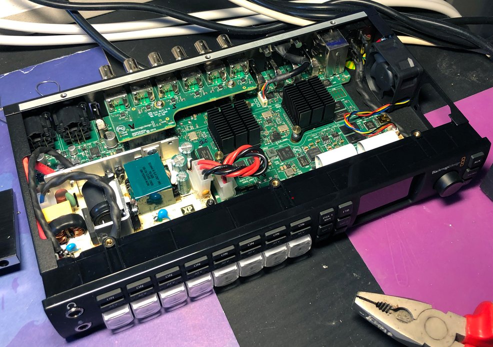
Fig.1 ATEM switcher's upper cover removed by removing its 10 black Phillips screws. Here one of the two original noisy fans is already removed.
The noise problem
The unit operates quietly most of the time, but once it heats up, the fans start running at full speed. The noise can become quite unpleasant, especially for those with sensitive ears. If the unit is in a distant location or inside a rack, the noise won't be much of an issue. However, if you work in close proximity to it, you may find the noise bothersome.
I found at least another unhappy user - with a silencing solution:
https://www.thingiverse.com/thing:3169393
This idea probably works, but I cannot directly recommend it - you risk some serious things:
- Dirt, liquids, or foreign objects can easily enter (though the huge fan openings) at the top, and destroy the circuits inside the unit.
- The EMC shielding is completely jeopardized when the solid metallic top cover (Faraday's shield) around the high-speed electronics is replaced with a plastic equivalent.
- The unit cannot be placed in a rack without reserving ample empty space above it, problematic especially if other equipment will be placed above.
- Even if the fan always runs at full speed there is no complete guarantee that the circuits run cool enough, since the original cooling path is completely removed.
To be honest, the thermal design of this unit is not up to par. It appears to be a little outdated and hasn't been improved since its introduction. My unit was purchased in 2020, but it was manufactured in 2016, which makes me wonder if the company was selling old stock.
The heavy computing task (video processing) is taken care of by two power-hungry Xilinx FPGAs, hiding under the finned heatsinks on the main PCB, see Fig.1. They dissipate the majority of the heat inside the unit. Their cooling relies solely on the fact that enough fresh air is pushed through the fins via their rather small heatsinks. To make the flow as efficient as possible, there is an airflow-controlling (plastic) viaduct mounted to the lid, see Fig.2.
The original (speed-controlled) 40mm fans were noisy, even at the lowest speeds. Unfortunately, due to the under-dimensioned heatsinks, the fans need to (and will) run practically at full speed. This generated an unpleasant and constantly disturbing noise. Don't even dream of performing a voiceover, or recording other faint sounds close to this unit.
First silencing attempt - replacing the fans
Replacing the fans with ultra-silent Noctua fans is a straightforward process. Always unplug the unit from the mains whenever the cover is removed. Remove carefully the old fans by unscrewing them and unplugging their cables from the main PCB. Attach the Noctua fans in the same orientation (blowing outwards, and rotated so that the wires come out from the bottom). Do not use the screws that came with the Noctua fans, they will fit but are too long and will collide with the lid when its replaced. Use the fan fixing screws that came with the unit.
The electrical wires, and their order, are the same. But beware - the colours of the wires are different. Since the Noctua fans come with another type of connector, you need to cut these away and reuse the connectors from the removed fans. Since it is practically impossible to rewire the old connectors, cut them from the old fans, and leave an inch or two of the original wires. See Fig.3 as an example of proper wiring. Make sure to solder properly all wires before shirking the heat-shrink tubes. Table.1 has the colours and wire functions listed (only valid for the listed Noctua fan):
Noctua wire color | Function | Original fan wire colors |
BLACK | GND | BLACK |
YELLOW | +12VDC | RED |
GREEN | Speed tacho out | YELLOW |
BLUE | Speed control PWM | BLUE |
Table.1 Fanl cable colors and functions
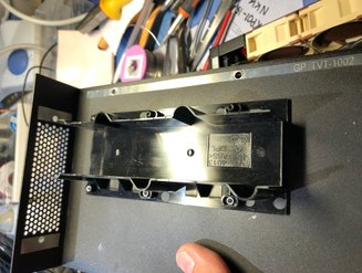
Fig.2 The air viaduct is essential for the cooling of the FPGA's. To prevent overheating, never run the unit for longer than a couple of minutes if the lid is open.
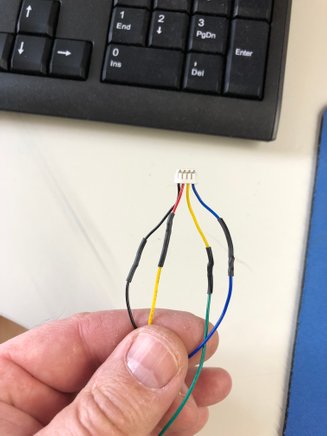
Fig.3 The colors differ but here is an example of the proper connection. Use heat-shrinkable tubing to guarantee goodisolation. Electrical tape is a no go.
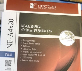
Fig.4 This is the proper Noctua fan type to use. Make sure it is the PWM model!
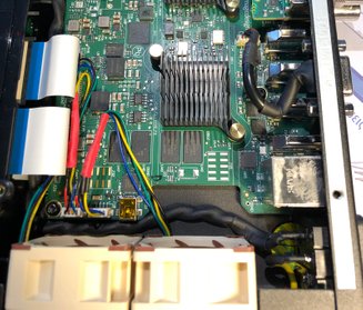
Fig.5 Noctua fans after proper installation. Make sure that the fan cables don't interfere with the air viaduct in the lid, before closing the same. The locations of the plastic walls are indicated in the silk-screen on the PCB.

Fig.6 The noise measurements were made using a Zoom X99 recorder with a fixed volume setting and no LP filter, at a distance of 30cm.
My initial test was performed with two Noctua fans, but types without the PWM speed control (just happened to have two of them). Such fans always run at full speed. Unfortunately, even these very silent fans produced quite loud noise at full speed, but the noise was more pleasant. The air exhaust ports in the top lid consist of small holes that make the exhaust air very turbulent. This produces additional noise. You can hear the difference by placing the lid temporarily in place. To drill open these air holes is not an option.
After replacing the fans with the correct type Noctua PWM fans (see Fig.4, Fig.5 shows the fans after installation) the unit was initially extremely quiet. But even these new fans will run at full speed when the unit heats up. The video mixer adjusts the fan speeds according to the FPGA temperature(s), and the new fans have similar flow rates as the old ones. Something else had to be done.
Second attempt - improving the heat conduction
Both the bottom and top covers are made of painted aluminium. Since aluminium is a good heat conductor it was obvious that conducting as much heat as possible from the FPGA's to the chassis - without removing the original air-cooling - was something to test.
This requires that you take apart the whole unit, mechanically modify some parts, and then put it back again. This procedure took me many hours, doing it carefully one step at a time. I hope these instructions get you up to speed if you decide to perform the modification yourself.
This thermal modification consists of actually three modifications:
- Improving the thermal transfer from the FPGA's to the heatsinks
- Connecting the FPGA's thermally to the bottom of the case
- Connecting the FPGA's heatsinks thermally to the top cover. This also improves the airflow through the heatsink fins.
TAKING THE UNIT APART
- Remove ALL BNC-connector's nuts and washers at the rear panel. This is a little tricky since the BNC-connectors are located very close to each other. By using a pair of long-nosed pliers (can be seen in Fig.1) it was easy to remove the nuts.
- Remove the 4 screws that secure the audio XLR connectors to the rear panel.
- Remove the small elevated PCB that holds the upper row of BNC-connectors by removing its two holding screws (seen in Fig.1). Carefully detach the PCB from its mating connector and pull out the PCB. Do NOT attempt to remove or unscrew the two metallic standoffs.
- Detach carefully ALL ordinary wire-based cables from the main PCB. It's a good idea to take pictures of everything before detaching, so you don't have to memorize how to put everything back. Never pull out the connector by just pulling from the wires.
- Next, remove the two ribbon cables (between the front panel and the main PCB) by detaching them from the main PCB. This must be done carefully by first opening their locking bars. This is done by carefully pulling the brown-colored plastic bars in the direction of the ribbon cable, away from the connector. They move only 1 to 2 mm. This opens the cable lock so that the cables can easily be pulled out.
- Remove the power supply by removing its 4 screws.
- Remove the black screws that hold the main PCB to the bottom of the unit. There should be 5 of them.
Now you should be able to remove the main PCB. You have to do it very carefully since both the BNC-connectors and the XLR-connectors are protruding inside the holes in the rear, so the PCB must be lifted up at the front side simultaneously when you slide it towards the front. Pull the incoming mains wire to the side from its clamps to make more room behind the front panel. It might be easier to remove PCB by first removing also the front panel assembly, by removing its holding screws. The XLR-connectors can also cause some trouble, see Fig.9 for more information.
THERMAL MOD 1 - A better thermal contact from FPGA's to the heatsinks
The FPGA's have thermal compound between them and the heatsinks. However, it was in my unit the ordinary white paste that is inferior compared to the thermal paste used CPUs and their heatsinks in PCs. Probably not a big issue, but decided to fix this to guarantee the best possible result.
- Remover the heatsinks (one at a time) from the FPGA's. This can be done by carefully pinching with small pliers the sprockets together on the PCB bottom side so that the brass part can slide through the PCB holes. Make sure not to damage the hole. See Fig.10.
- Clean away the old thermal paste using a cotton swab and alcohol (or isopropanol). Make sure not to leave any residue or cotton fibers on the surface.
- Clean the heatsinks the same way.
- Apply a supple amount of the good quality thermal paste on top of the FPGA's and replace the heatsinks. Move them sideways several times so that the thermal paster sets. Make sure the holding sprockets locks securely back.
THERMAL MOD 2 - Heatsinking the FGPA's to the bottom cover
This is the most important thermal modification. You could probably only do this mod and forget the two others, but for the best effect, I recommend you perform all three.
- Cut the 4mm thick thermal gap filler to size (same size as the FPGA's - note that the FPGA's are of different sizes. If too small then the thermal transfer is not optimal, if too big (so that other high profile surrounding components gets covered by it) then it will not fit properly between the PCB and the bottom, and cause unnecessary and harmful bending to the PCB.
- Place the thermal gap filler with the white sticky side against the PCB. Remember to first remove the protective plastic. Before attaching, make sure that the surfaces are completely clean and free from any conductive particles, see Fig.10.
- Do the same for both FPGA locations. Push the thermal mats gently against the PCB so that the stick and will stay in place even if the PCB is facing downwards. Use a counterforce on the other side (the heatsink). It is of utmost importance not to bend or cause any physical stresses to the main PCB.
- For the best effect - scrape away the black paint from inside the bottom cover, at those locations where the thermal gap filler will come into contact with the bottom. This is not required but improves the heat transfer remarkably. After removing the paint (and properly also some aluminum) make sure to remove all particles and dust with an air blower (or vacuum it).
THERMAL MOD 3 - Heasinking the heatsink to the top cover
The most efficient way would have been to remove the heatsinks and replace them with solid aluminum blocks, having a direct thermal path to the top cover. This would have required specially manufactured parts so I scrapped the idea.
I also noticed that part of the airflow escapes the heatsink, there is a gap above the fins inside the "wind tunnel". The solution is to fill this gap - all the way to the top lid. This requires a small modification
- Remove the air viaduct from the top cover (Fig.12).
- Cut (saw) and remove the center part as shown in Fig.13.
- Scrape the black paint from the inner side of the top cover at the location that is defined by the heatsink area, see Fig.14.
- Cut 4 equally sized pieces of the same thermal mat that was used under the FPGAs. The width must be the same as the width of the air viaduct, the length such as it reaches over both heat sink fins. Leave the top cover upside down for now.
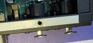
Fig.9 You might have to slightly bend the XLR-connector's locking brackets, to be able to pull them through the back panel holes. Bend them just as little as needed, they are brittle.
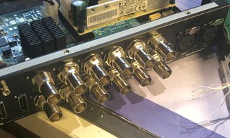
Fig.8 Remove all BCN-connector nuts and washers, as well as the XLR-conector's screws.
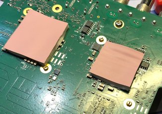
Fig.10 Heatsink holding sprockets seen from the underside. Here the 4mm thick thermal gap fillers are already put into place.
Fig.11 Proper thermal paste.
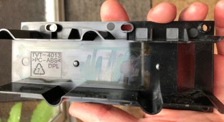
Fig.12 Original air viaduct removed from the top cover (6 screws removed).
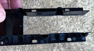
Fig.13 Modified air viaduct with the centre part cut away to open a path all the way to the top cover inside surface.
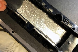
Fig.14 Paint removed from the surface of the inside of the top cover, after the viaduct is put back.
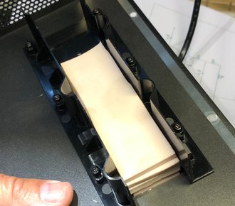
Fig.15 Four cut-to-size layers of thermal gap filler is placed into position. Their thickness fills nicely the complete gap between the top of the heatsinks and the top cover.
Reassembling the unit
It is time to reassemble everything now that all three (or at least modification 2) are performed.
REPLACING THE PARTS
- Re-insert the PCB. Make sure that the thermal pads you placed under the PCB stay in place during the PCB inserting phase. Hold on to them as long as possible, or do the insertion of the PCB upside down. Make sure not to damage the XLR brackets when inserting them into their rear panel holes. This is a little tricky. You might have to bend them slightly (as you probably did already during the disassembly).
- After the PCB is in place check that the PCB fixing holes align with their respective standoffs, but do not attach the screws yet.
- Next assemble the XLR-screws, and all the lower row BNC-connector washers and nuts. Tighten them up with about the same torque you used to loosen them.
- Now attach the PCB holding screws (5 pieces).
- Attach the power supply using its 4 screws, make sure that the orientation is correct, the +12VDCoutput must face the main PCB.
- Make sure that the two metallic standoffs are firmly screwed to the main PCB, before attaching the upper SDI/BNC-output board. Glide the BNC-connectors in their holes and carefully reinsert the connector that mates the upper PCB to the main PCB. After properly inserted, attach the BNC-washers and nuts, and thereafter the two fixing screws.
- Reconnect the two ribbon cables that connects the front panel to the main PCB. Make sure the connector locks are fully open before inserting the ribbon cables. The cable must be inserted in a straight angle. Make sure the cables are fully inserted before closing the locks by pushing them towards the connector body.
- Connect all other wires back (mains input to the AC/DC PSU, the output from the PSU to the main PCB, the phones and mic cables from the front panel to the main PCB). Check your photos if you are not sure how they were connected. Make sure all connectors are fully inserted and properly locked.
Final check
Before closing the lid it is advisable to check the proper operation of the unit by powering it up and testing all functions. Before applying power it is advisable to double-check everything and compare the unit with the photos that you took before the disassembly. Connect the mains cable and at least one video source and preferably also a preview monitor. Do not touch any parts inside the unit when the lid is open and power is applied. Turn on the power and check that the unit wakes up normally and that both fans start to spin (slowly). Check that the unit works normally by using the front panel buttons and that there is an image on the small front panel display.
If all seems to be in order, turn off the power and proceed with closing the lid. Because the thermal gap filler is heavy and does not stick to the lid, the only easy and working way of closing it is to do it upside down.
External modification
to be continued...
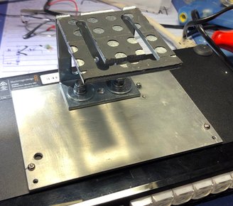
Fig.16 External fixing plate and standoff. This plate has a double function in my system. The aluminium plate acts as a heatsink (yes - there is thermal paste between it ant the unit bottom), but also as a convenient standoff to elevate the unit about 10cm above the table surface.
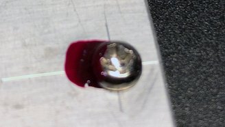
Fig.17 The M3 screws that attached the unit to the bottom plate are so short that they cannot be tightened at high torque, and can, therefore, become loose. Locking the screws is a must, ordinary nail polish works great (any color would do :).
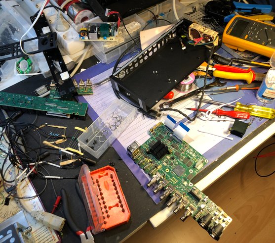
Fig.7 This modification requires that you take apart the whole unit, everything else than the front panel. In this picture its also taken apart - but for another non- relevant reason). Disassembly in not very complicated but you have to be very careful and follow proper ESD handling precautions. If you don't know what that word means, please don't attempt this modification.

Copyright @ DEXTREL / 2020 / All Rights Reserved