Neumann U-47 Condenser Microphone Power Supply
Highlighted features
- Precisely regulated +105VDC voltage
- Less than 200uV output ripple & noise
- Capable of driving simultaneously 6 U-47 microphones (50W of power)
- Foldback current limiting - withstands constant short circuits on all outputs.
- Uses standard and easily available components.
- Soft turn on
- Low parts count
Background
Many people still use the original, refurbished, or "cloned" Neumann U-47 microphones around the world. Despite the existence of modern large-diaphragm microphones, they struggle to match the original U-47's "deep" and "warm" sound. However, finding a functional power supply for the original microphone can be challenging. Even if you do lay your hands on one, it may have dried electrolytic caps and outdated components and degraded insulation, which could pose a hazard. Additionally, the original PSUs had some residual output voltage ripple due to the purely passive (LCR-filter) voltage regulation. Their output voltage was also dependent on the loading. As a result, there is a need for a modern, appropriate power supply that can feed multiple microphones and that performs better than the original and uses non-exotic components.
IMPORTANT WARNING
The power supply and its outputs and cabling contain lethal voltages. I cannot be kept responsible for any injuries or deaths caused by not following proper safety measures. Please note that high DC voltages are especially dangerous!
This project is not intended for beginners.

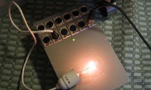
Fig.1 Prototype testing with a incadescent bulb as a load.
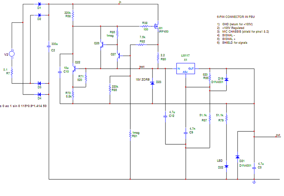
Fig.2 Schematic of the 6 microphone U-47 power supply. Pardon for the bad quality picture.
About the circuit
To power the PSU it's strongly recommended you use a toroidal transformer to minimize its stray magnetic field and the risk of inducing hum to close-by wiring. The transformer should have a 110...120VAC secondary and a primary voltage compatible with the voltage in your region (100, 115 or 230VAC). Even if it looks tempting to use directly the 115VAC mains, it's essential to use a transformer to ensure the required isolation.
When selecting the transformer, choose one that is rated at least 8 watts per microphone. For instance, if there PSU will be used for 6 microphones at least a 50 Watt transformer would be necessary.
The transformer output feeds a plain vanilla full wave rectifier D1-D4. Use >= 1A and at least 200V type diodes (1N4003 to 1N4007 are fine). You can also use a readily available bridge rectifier with a minimum 2A/200V rating. To prevent transformer secondary ringing due to the rectifier diode reverse recovery, it is recommended to connect a 100nF/250VAC polyester or polypropylene capacitor across the input of the rectifier bridge (NOT shown in the schematic in Fig.1).
The full-wave rectifier output is connected to the smoothing electrolytic capacitor C2. This capacitor is rated at 330uF/200V for 6 microphones, but the capacitance can be reduced if you drive fewer mics. A single microphone PSU could do with a 68uF/200V capacitor. The ripple of across C2 during maximum load should never become too large so that the valley can never drop below +120V. This ensures proper regulation and a very low output voltage ripple.
To achieve as small as possible output ripple, two active regulators are connected in series. The second regulator further regulates the first regulator's output. The first regulator is an N-channel high voltage power MOSFET transistor M1 (IRF450) that handles the pre-regulation - and the majority of the voltage drop. The second regulator, which regulates the final voltage and also limits the maximum output current, is the well-known LM117 or the cheaper equivalent LM317 (with slightly worse precision).
The maximum allowed voltage across LM117 is 40 volts, but is limited in this circuit to about 12 volts. You can use the LM317 but you have to probably trim R67 to achieve a precise +105VDC at the output.
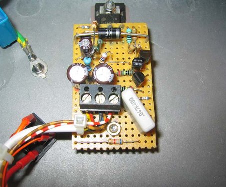
Fig.4 Detail of the assembled perfboard prototype.
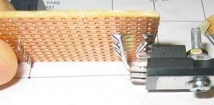
Fig.3 Detail of "piggyback" mounting of the LM117 regulator located "thermally" on top of the MOSFET. Make sure to isolate the regulator tab from the M3 fixing screw, using a plastic isolating washer designed for this purpose.
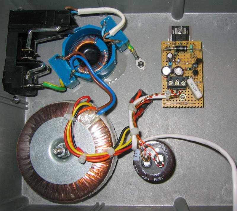
Fig.5 Layout of the prototype. Note the placement of the main parts. A mains input differential filter is strongly recommended, as shown here. The goo that attaches the filter and the electrolytic capacitor to the bottom of the aluminum case is epoxxy. Never use hot-melt glue for this!
Important notes
- The power MOSFET must be mounted on a heatsink and must be properly and carefully isolated from the heatsink (using Silpad or similar isolating but heat-conducting material). The MOSFET drain (the body) sits at the input DC voltage potential. If you use the chassis as the heatsink (or have a separate heatsink that is NOT isolated from the metal chassis) then also protective earthing is MANDATORY. It's a good idea to isolate the pass transistor even when using a separate isolated heatsink.
- Mounting the LM117 (or LM317) regulator on top of the pass transistor provides additional safety and overtemperature protection (the pass transistor heats up the regulator that will go into overtemperature protection - if these run too hot together). The regulator's metal lug MUST be isolated from the screw, especially if the screw connects mechanically to the chassis.
- The output voltage must be verified and Rxx adjusted accordingly to achieve +105VDC. Do NOT use a trimmer potentiometer in this location to guarantee stability and low noise! Just select an appropriate fixed resistor or a combination of them.
- A common mode mains filter is recommended for serious studio use, especially in environments where the mains voltage iscan contaminated with repetitive noise (light dimmers, motor drives etc.).
- Do not use hot-melt melted glue for the assembly of any components! The stuff that is visible in Fig5 under the mains filter and the electrolytic capacitor is two-component epoxy.
- Make sure that no mains-voltage carrying wires can come in contact with the secondary side wiring if they would become loose.
To be continued...
Copyright @ DEXTREL / 2023 / All Rights Reserved